

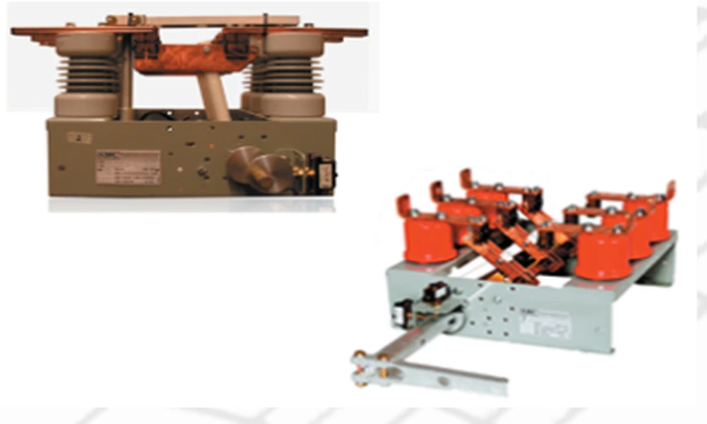
Industrial electrical systems depend on equipment with clearly defined switching roles. A device that isolates a circuit does not automatically perform the same job as one designed to interrupt current. For engineers evaluating high-voltage equipment, matching the switch to its intended duty is a basic part of planning a distribution system.
Becker Mining USA lists visible disconnect switches for non-load-break applications through 15 kV. That description makes the application boundary clear: the disconnect provides visible separation, while another suitable device handles current interruption before the switch blades move. The switch should therefore be evaluated as part of a coordinated arrangement, not as a stand-alone replacement for interrupting equipment.
In a distribution layout, equipment schedules and diagrams can clarify which component interrupts current, where isolation occurs, and what signal coordinates the sequence. That context helps reviewers check a disconnect against upstream and downstream equipment instead of comparing nominal voltage in isolation. The specific design still needs to be confirmed against its full ratings and installation requirements.
The product information also describes an auxiliary switch on the handle. It operates before the disconnect blades, allowing another device to interrupt the circuit first. This sequence links the disconnect’s mechanical operation with the wider switching arrangement. When reviewing a system, teams can consider what equipment will perform the interruption, how the auxiliary switch fits the control sequence, and whether the selected configuration matches the intended application.
A voltage rating is only one specification to check. The required switching duty and the relationship between the disconnect and other devices also matter. A non-load-break switch should not be selected on the assumption that it will interrupt load current. Confirming that distinction early can help teams compare equipment according to its stated function and avoid treating different device types as interchangeable.
Becker Mining USA’s product page lists visible disconnects alongside options and devices such as auxiliary switches, undervoltage and shunt-trip devices, and fuseholders. The page describes these features at the product-family level, so the appropriate configuration depends on the specific switch and application. Engineers can use those details to frame a technical review, then confirm the required ratings and options against the applicable product specifications.
When assessing a visible disconnect for a project, a review can start with a few practical questions:
- Is the application non-load-break, and which device will interrupt current?
- Does the switch’s voltage rating fit the system?
- How will the auxiliary switch coordinate with the intended operating sequence?
- Which optional components are relevant to the specific configuration?
These questions help keep component selection tied to the system’s actual requirements. Teams beginning that review can consult Becker Mining USA’s high-voltage disconnect information.
